
Discover the unprecedented possibilities of the Software Defined Antenna.
The world at your fingertips with one compact antenna
Discover the unprecedented possibilities of the Software Defined Antenna.
The world at your fingertips with one compact antenna
Here you can read everything about the Software Defined Antenna, including practical matters, capabilities, additional information, optional components, and troubleshooting. You can find the manual here in Dutch and English.
Click directly on the topic below or scroll through the page.
Mogelijkheden
Ontdek wat er allemaal mogelijk is met de antenne en de bijbehorende software.
What are the capabilities of the Software Defined Antenna?
The antenna of an SDA is spherical and has a diameter of approximately 80 cm. Due to its small dimensions, it is easier to keep potential sources of interference at a distance. The antenna is fixed. For frequencies from 3 to 30 MHz, the antenna maps the electromagnetic field (EM field) in three dimensions. These raw signals are digitized, after which the information is further processed. As a result, various radiation patterns can be realized in the horizontal plane.
For example, omnidirectional. A special form of this is 'Spatial'. In this case, a 'stereo image' of the EM field is converted into audio, so that signals originating from different directions are heard in different directions. The optimal phase difference can be selected using the INVERTED button.
A loop antenna can also be created. The direction is determined by software. Therefore, there are no mechanical limitations on the rotation speed.
Similarly, a directional antenna can be configured. The beam can be rotated in any desired direction by software. The angular aperture of the antenna can be set from approximately 69° to 29°, with a corresponding gain of 3 dBd to 12 dBd. Special combinations of radiation patterns are also possible; think of a beam direction in the desired DX, with a deep zero towards some annoying interference source.
To make such antenna diagrams possible, it is necessary that the digital antenna is integrated into a Software Defined Receiver. Therefore, an SDA also includes a complete high-end shortwave receiver.
What are the capabilities of the SDA?
The antenna of an SDA is spherical and has a diameter of approximately 80 cm. Due to its small dimensions, it is easier to keep potential sources of interference at a distance. The antenna is fixed. For frequencies from 3 to 30 MHz, the antenna maps the electromagnetic field (EM field) in three dimensions. These raw signals are digitized, after which the information is further processed. As a result, various radiation patterns can be realized in the horizontal plane.
For example, omnidirectional. A special form of this is 'Spatial'. In this case, a 'stereo image' of the EM field is converted into audio, so that signals originating from different directions are heard in different directions. The optimal phase difference can be selected using the INVERTED button.
A loop antenna can also be created. The direction is determined by software. Therefore, there are no mechanical limitations on the rotation speed.

Similarly, a directional antenna can be configured. The beam can be rotated in any desired direction by software. The angular aperture of the antenna can be set from approximately 69° to 29°, with a corresponding gain of 3 dBd to 12 dBd. Special combinations of radiation patterns are also possible; think of a beam direction in the desired DX, with a deep zero towards some annoying interference source.
To make such antenna diagrams possible, it is necessary that the digital antenna is integrated into a Software Defined Receiver. Therefore, an SDA also includes a complete high-end shortwave receiver.
Using the Software Defined Antenna
When used by an amateur radio operator, you can expect that (many) antennas are positioned or mounted close by. In that case, resonances near the antennas may cause the EM field to be significantly distorted. The consequence of this is that the SDA produces errors in the direction of the signals. If the distortion is limited, the antenna can be calibrated using a beacon transmitter, which automatically compensates for the EM field distortion. Avoid current maxima of other nearby antennas.
The converter outputs data to the PC without interruption. After all, reception also continues uninterrupted. When using older PCs, it may be important that the PC is started up before the converter is enabled. This prevents the PC being confronted with a large amount of data before it is ready, and the startup fails. This effect no longer occurs in Windows 11.
In combination with a transmitter, a PTT link can be established with the SDA. The SDA then switches off when the transmit key is pressed. This disables the audio and also protects the system as much as possible against strong signals.
The hardware of the control unit is equipped with a CAT interface. A transceiver can be connected to this. In the event of suitable equipment, the SDA will then follow the frequency of the transceiver.
With the use of an SDA, information regarding the direction of the signal can be reported directly, especially for signals at somewhat longer distances. A whole new dimension becomes available when the propagation paths can also be included in the report. Especially if that happens from two or more stations. Such a report then offers a much better insight into what happens during propagation.
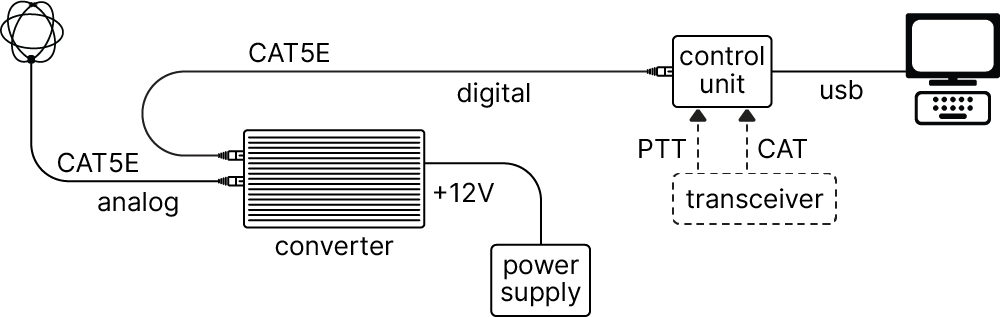
Hardware overview
Multi-antennas
An SDA can simultaneously construct multiple different antennas from the raw antenna data. The number of antennas that can function simultaneously in this way depends on the computing power of the PC. In this SDA, a maximum of four antennas simultaneously was chosen. As a result, the requirements for the PC are not spectacular, and virtually any PC can be used.
An important function made possible by this is the 'signal diagram'. This involves creating an extra beam antenna that rotates at a speed of 10 times per second and takes a signal strength measurement every eight degrees. The results of all these measurements are plotted on the azimuthal map. This allows you to see signals arriving from all directions that you can hear with the receiver. If you want to extract a signal from this, you can point the antenna in beam mode in the desired direction.
During, for example, a round table or a contest, signal directions usually make large jumps when switching transmitting stations, falling outside the angular aperture. In tracking mode, these large angle differences will not be followed. The 'following' mode is better suited for this. In that case, the beam will automatically always focus on the strongest signal. However, when multiple signals are present on the frequency simultaneously, this can lead to the unwanted signal being selected.

Propagation
Of particular interest, of course, are the various propagation paths that can be made directly visible with the 'signal diagram'. What is immediately noticeable is that with short skip, usually no specific direction is found at all. That is logical, of course; the signals come almost directly from above. Only as the distance from the transmitter increases does a direction begin to become discernible. At distances from 500 to 1000 km, the direction is clearly discernible, especially when the angle at which the signals arrive is somewhat lower. At good conditions, the connection usually turns out to run almost in a straight line. If conditions deteriorate somewhat, you usually see the direction change immediately. If the direct signal path drops out to a greater or lesser extent, another path sometimes becomes stronger via a detour. If a signal comes in via the long path, that is of course also immediately visible: the signal is then coming from exactly the other side.
It may occur that interference arrives at a low radiation angle, while the desired signals arrive at a high angle. In such a case, a horizontal dipole or inverted V can provide better reception, because such an antenna suppresses low radiation and favors the desired signal. However, when the desired signals come from a defined direction, and especially when the signals arrive at a somewhat lower radiation, it turns out that a signal with a horizontal dipole is barely receivable while the SDA delivers a comfortable signal.
Options
Repeater

Beacon transmitter
Mini beacon transmitters are available that transmit a carrier every MHz. These beacons are intended to verify proper functioning. It sometimes happens that a transmitter with a known location is received from such an unusual direction at a certain moment that the operation of the SDA is called into question.
For example, because an unusual resonance has arisen in another antenna. To verify this, the beacon from a similar direction and frequency can be used to check from which direction the beacon is being received. In this way, certainty regarding the SDA can be obtained.
The transmitter can be supplied in the form of a small PCB. The battery (9V), an antenna (1 to 3 meters), and ground (wire, plate, or pin) must be provided by the user.
Calibration transmitter
The calibration transmitter is intended to calibrate an SDA for EM field distortion. Like a beacon transmitter, this transmitter emits a signal at every MHz. However, the carrier is switched on and off at a precise rate, allowing the calibration software to check whether there are excessive interference signals present at the measurement frequency.
With a jumper or a switch, a calibration transmitter can be converted into a beacon transmitter without interruption, so that the test function can also be used.
The transmitter can be supplied in the form of a small PCB. The battery (9V), an antenna (preferably 3 meters), and ground (wire, plate, or pin) must be provided by the user.
Options
Repeater
Beacon transmitter
Mini beacon transmitters are available that transmit a carrier every MHz. These beacons are intended to verify proper functioning. It sometimes happens that a transmitter with a known location is received from such an unusual direction at a certain moment that the operation of the SDA is called into question.
For example, because an unusual resonance has arisen in another antenna. To verify this, the beacon from a similar direction and frequency can be used to check from which direction the beacon is being received. In this way, certainty regarding the SDA can be obtained.
The transmitter can be supplied in the form of a small PCB. The battery (9V), an antenna (1 to 3 meters), and ground (wire, plate, or pin) must be provided by the user.
Calibration transmitter
The calibration transmitter is intended to calibrate an SDA for EM field distortion. Like a beacon transmitter, this transmitter emits a signal at every MHz. However, the carrier is switched on and off at a precise rate, allowing the calibration software to check whether there are excessive interference signals present at the measurement frequency.
With a jumper or a switch, a calibration transmitter can be converted into a beacon transmitter without interruption, so that the test function can also be used.
The transmitter can be supplied in the form of a small PCB. The battery (9V), an antenna (preferably 3 meters), and ground (wire, plate, or pin) must be provided by the user.
Solving problems
| Symptom | The SDA is doing absolutely nothing |
| Cause | The transceiver is switched off and is connected to the SDA |
| Cause | The converter has no power |
| Cause | One of the cable connections is loose |
| Symptom | Starting the PC shows strange phenomena |
| Solution | Let the PC start up first and then switch on the converter |
| Symptom | The control unit does not switch on |
| Cause | The PC started while the PTT was activated because the transceiver is off |
| Solution | Switch on the transceiver or disconnect the PTT connection |
| Symptom | The frequency indication does not synchronize with the display. |
| Cause | When the SDA software is closed and restarted, the converter retains the old frequency. |
| Solution | Enter a new frequency |
Solving problems
| Symptom | The SDA is doing absolutely nothing |
| Cause | The transceiver is switched off and is connected to the SDA |
| Cause | The converter has no power |
| Cause | One of the cable connections is loose |
| Symptom | Starting the PC shows strange phenomena |
| Solution | Let the PC start up first and then switch on the converter |
| Symptom | The control unit does not switch on |
| Cause | The PC started while the PTT was activated because the transceiver is off |
| Solution | Switch on the transceiver or disconnect the PTT connection |
| Symptom | The frequency indication does not synchronize with the display. |
| Cause | When the SDA software is closed and restarted, the converter retains the old frequency. |
| Solution | Enter a new frequency |