Software Defined Antenna makes it possible to create radiation patterns for shortwave reception, using an antenna smaller than one meter, ranging from an omnidirectional antenna, magnetic loop, to a beam antenna with a gain of 3 to 12 dBd.
Software Defined Antenna makes it possible to create radiation patterns for shortwave reception, using an antenna smaller than one meter, ranging from an omnidirectional antenna, magnetic loop, to a beam antenna with a gain of 3 to 12 dBd.
Everything from our own location
Software Defined Radios (SDRs) have now become commonplace within the world of amateur radio. Signal processing is then performed partly digitally. In that case, digital signal processing determines the characteristics of the receiver. This results in significantly more possibilities and flexibility.
Similarly, an innovative development has taken place in the field of antennas: the Software Defined Antenna (SDA). Such antennas do exist, but they require an antenna much larger than the wavelength. The SDA under discussion here differs fundamentally from this: the antenna is much smaller than the wavelength – making it particularly suitable for applications on the HF bands.
The direction and angular aperture of the beam antenna can be controlled using the software. The antenna is fixed and does not need to rotate physically.
From the raw antenna information, multiple different antennas can be created simultaneously, allowing independent functions to be realized.
Because the signal processing of the antenna data takes place largely digitally, many new possibilities can be realized.
The SDA contains a complete receiver. In addition to extensive graphical information, a high-quality shortwave receiver is integrated into the SDA.

The SDA has a special antenna. A number of loop antennas are incorporated into it, and the antenna is fixed.
The three HF signals derived from three dimensions of the EM field are transmitted symmetrically via a CAT5 cable and fed to the converter for further processing. The preamplifiers are powered by the converter via the same cable.
The three antenna signals are brought in via the 'ANT' connector of the analog-to-digital converter. The signal is passed through the DATA connector and continues via CAT5, but now digitally.
This serial data is routed to the control unit. Protection has been provided in case the CAT5 cables are exchanged.
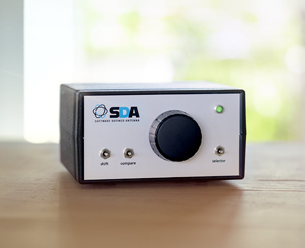
The control unit features a few common controls, such as the dial knob and three switches. It can be set to two modes: receiver and antenna mode.
The control unit sends all control information, along with the digital antenna signal, to the PC via USB. This makes it possible to simulate the behavior of all previously mentioned antenna types.

The PC provides a graphical presentation on the screen. The necessary keys for the antenna and receiver settings are present here. Additionally, an azimuthal map is displayed that can be zoomed in and out. In this map, signal strengths are plotted from all directions in multiples of 8°. In beam mode, the angular aperture and direction of the antenna are visible on this map.
The SDA has a special antenna. A number of loop antennas are incorporated into it, and the antenna is fixed.
The three HF signals derived from three dimensions of the EM field are transmitted symmetrically via a CAT5 cable and fed to the converter for further processing. The preamplifiers are powered by the converter via the same cable.
The three antenna signals are brought in via the 'ANT' connector of the analog-to-digital converter. The signal is passed through the DATA connector and continues via CAT5, but now digitally.
This serial data is routed to the control unit. Protection has been provided in case the CAT5 cables are exchanged.
The control unit features a few common controls, such as the dial knob and three switches. It can be set to two modes: receiver and antenna mode.
The control unit sends all control information, along with the digital antenna signal, to the PC via USB. This makes it possible to simulate the behavior of all previously mentioned antenna types.
The PC provides a graphical presentation on the screen. The necessary keys for the antenna and receiver settings are present here. Additionally, an azimuthal map is displayed that can be zoomed in and out. In this map, signal strengths are plotted from all directions in multiples of 8°. In beam mode, the angular aperture and direction of the antenna are visible on this map.
The SDA is an advanced compact antenna that registers received signals in three dimensions for shortwave from 3 to 30 MHz. Based on this, the SDA uses advanced digital signal processing, allowing various radiation patterns to be formed, such as omnidirectional, loop antenna, directional antenna, and combinations thereof.
A loop antenna can suppress interference from a single direction, thereby reducing the nuisance caused by a local interference source.
The directional antenna can be set to a gain of 3 to 12 dBd, with the beam angle varying from 69° to 29° respectively. For long-distance traffic with lower radiation angles, this can significantly improve reception.
Instead of a physical rotor mounted with a directional antenna, the direction of the SDA is determined electronically. This allows the SDA to change direction in milliseconds, incomparable to conventional antennas.
The advanced digital signal processing performs the entire reception process. SDA therefore also includes an SDR. The available modes are LSB, USB, CW, and Auto, where LSB is selected below 10 MHz and USB above 10 MHz. The audio output displays the received signals.
The SDA delivery consists of the antenna, the converter, the control unit, and the software for the PC. Additionally, CAT5 cables, a USB cable, a PC, and optionally a beacon transmitter are required.
The antenna is spherical and has a diameter of approx. 80 cm.
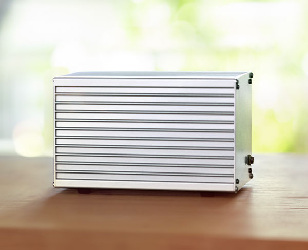
The converter measures approx. 170x11x10 cm. This device consists of three high-quality shortwave receivers followed by six ADCs. The converter requires a power supply of 12 V at max. 2 A.
The control unit contains the controls and processes the digital information between a PC and the converter.
The antenna is spherical with a diameter of approximately 80 cm. A CAT5 cable can be clicked into the antenna. The antenna can be mounted on a mast and the cable threaded through it.
This CAT5 cable (max. 30 meters) is connected to the converter in a dry location; the shack could also serve this purpose. This converter must be powered by +12 VDC and consumes a maximum of 2 A. Following the converter, a second CAT5 cable (max. 20 meters) runs to the control unit in the shack. The control unit is positioned next to a PC connected via a USB cable. This PC is connected to loudspeakers.
Follow the installation manual for optimal grounding and placement.
The SDA can virtually simulate multiple antennas simultaneously. This means that you can, for example, listen to a signal from a specific direction while simultaneously another antenna is rotating rapidly and plotting the measured signal strength from the detected direction on the azimuthal map. While listening, you can then see where the signals are coming from. In addition to the RST report, the signal direction can also be reported.
The SDA can use digital signal processing to suppress interference from certain directions and amplify signal from the desired direction, resulting in a better signal-to-noise ratio. This is particularly useful on busy shortwave frequencies and for local interference.
Yes, 12 presets are possible. Frequency, mode, antenna mode, and optional antenna direction with angular aperture.
Yes, that is possible for 49 ICOM models.
The SDA operates within the shortwave frequency range of 3 to 30 MHz. This makes the system ideal for both amateurs and professional radio users working in this frequency spectrum.
Digital signal processing improves reception accuracy and flexibility, specifically suppresses unwanted signals, and enables dynamic adjustment of gain and directional patterns, significantly improving performance and creating possibilities that were previously unavailable.
The SDA requires little maintenance. Pay attention to any antenna grounding, connectors, especially outdoors, and any software updates. Take into account changes to physical obstacles that could interfere with signal reception.
Standard system: €2,240.-
The system is supplied with antenna, converter, control unit, and software.
Beacon transmitter: €20.-
The transmitter can be supplied in the form of a small PCB. The battery (9V), an antenna (1 to 3 meters), and ground (wire, plate, or pin) must be provided by the user.
Calibration transmitter: €30.-
The transmitter can be supplied in the form of a small PCB. The battery (9V), an antenna (preferably 3 meters), and ground (wire, plate, or pin) must be provided by the user.
The SDA uses a special antenna. It is shaped like a sphere with a diameter of approximately 80 cm. It incorporates several loop antennas and is fixed in place, with the N-marking oriented towards the north. The antenna can be mounted on a mast with a maximum diameter of 48 mm.
Since predictable phase and amplitude behavior is necessary over a relatively wide frequency range, no resonant elements have been used and a preamplifier is required. This amplifier must process the entire shortwave spectrum, and therefore the large-signal behavior must be suitable for this.
Grounding of the antenna can be done via the mast and/or the cable shielding. Noise and resonance from the grounding must be avoided.
The three HF signals derived from three dimensions of the EM field are transmitted symmetrically via a CAT5 cable and fed to the converter for further processing. The preamplifiers are powered by the converter via the same cable.
The three antenna signals are fed into the converter via the 'ANT' connector. Inside the converter, the signals are reduced in bandwidth using switchable parallel band filters to prevent intermodulation. There, the signals are digitized using six 24-bit analog-to-digital converters. The information is output serially by the converter.
The signal from the DATA connector continues via CAT5, but now digitally. The serial data is routed to the control unit. Protection has been implemented in case the CAT5 cables are interchanged to the converter, which would cause the antenna power supply voltage to end up on the data interface.
The converter requires an external power supply of +12V at 2A.
The control unit features several common controls, such as the dial knob and three switches. It can be set to two modes: receiver and antenna mode.
In receiver mode (the LED is red), the frequency can be set using the dial knob in 1 kHz increments or, together with the shift key, in 10 Hz increments. If desired, 500 Hz can be selected for the coarse step size. When the dial is turned quickly, the step size increases. In this way, it is possible to change the frequency quickly.
In antenna mode (the LED is green), the dial knob functions as the rotor control. This rotor can be adjusted at unlimited speed. There is also no stop at north or south; it can be rotated continuously. When the shift button is pressed, the angular aperture of the beam can be adjusted using the dial knob. Naturally, this also changes the gain of the beam.
The control unit sends all operating information, along with the antenna data, to the PC via the USB connection. The PC processes the data from the antenna using digital signal processing. This makes it possible to realize the behavior of all previously mentioned antenna types.
The PC handles the digital signal processing required to realize the desired radiation patterns and for the integral shortwave receiver.
Furthermore, the PC offers a graphical presentation on the screen. The necessary buttons for the antenna and receiver settings are present here. Additionally, an azimuthal map is displayed that can be zoomed in and out. On this map, signal strengths can be plotted from all directions in multiples of 8°.
In loop antenna mode, the antenna can be rotated and the zero directions are visible on the map. In beam mode the angular aperture of the antenna and the direction in which the antenna is pointed are displayed. Furthermore, a combination of the two is possible. In this case, the direction can be set independently of the maximum and minimum: the beam/loop mode.
The audio from the receiver is available at the audio output.
Many functions can be accessed not only with on-screen buttons but also via shortcuts on the keyboard.